


Software drivers for automotive powertrain in microcontroller AURIX 2G
This software forms the framework for the integration of fail-operational control algorithms and multiphase motor diagnostic algorithms generated from the environment of MATLAB/Simulink on the AURIX 2G six-core microcontroller platform for high safety applications. This makes it possible to test the drive control in the event of a fault in a real application with a real motor and inverter. The main parts of the SW are structured peripheral drivers of the AURIX 2G microcontroller based on iLLD (PWM module, SAR and DS AD converters, GPIO) for two subsystems of a multiphase motor (two three-phase motors).
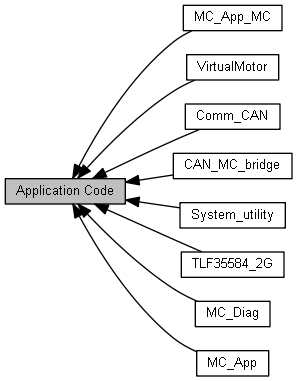
Figure 1: Structure of the drivers
Statically defined peripheral configurations enabling adaptation of the final HW of a specific power converter. The use of fast communication buses of sensing circuits of controlled variables with high resolution (SPI current sensors, I2C voltage and temperature measurement) is considered.
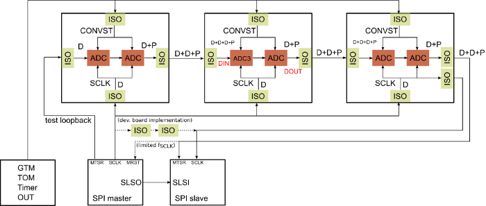
Figure 2: Realization of the isolated SPI module for the measured data gathering
Part of the design of the microcontroller peripheral driver’s SW is also the design of a map of the connection of the microcontroller pins to the individual subsystems of the inverter with regard to the suppression of the effect of common-cause failure (HW). For communication with the superior system, the CAN communication bus is implemented, which is defined using DBC files. The controls of the individual peripherals used to control the motor allow the test mode to be activated. In this test mode, the physical signals are replaced by the signals of a virtual motor, which is implemented in the SW and is run on one of the free cores of the microcontroller. The virtual motor allows real-time testing of the entire motor control loop before using algorithms on a real power converter.
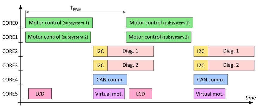
Figure 3: Distribution of algorithms in the cores of AURIX microcontroller
Technical parameters:
- Designed for multiphase PMSM control algorithms testing, created in MATLAB/Simulink with generated C code.
- Ready for the redundant architecture of two subsystems (2x3 phase converter and motor) to increase reliability.
- Structured peripheral controllers of the AURIX 2G microcontroller with the static definition of subsystem configuration.
- Design of microcontroller pin layout to subsystems with respect to common HW errors.
- CAN communication with the superior system using the CAN bus defined by DBC files.
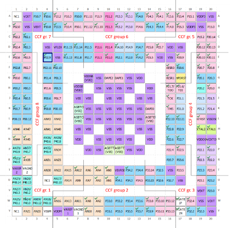
Figure 4: Pin layout with respect to common HW errors